Posted by kishorechurchil in verilog code for adder and test bench Tagged: adder, test bench, Verilog Code, verilog code for adder and test bench Post navigation.
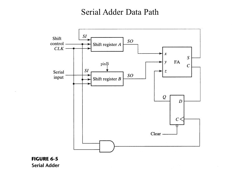
Normally an N-bit adder circuit is implemented using N parallel full adder circuits, simply connected next to each other. The advantage of this is that, the circuit is simple to design and purely combinatorial. Another way to design an adder, would be to use just one full adder circuit with a flipflop at the carry output.
The circuit is sequential with a reset and clock input. In each clock cycle, one bit from each operand is passed to the full adder, and the carry output is fed back as the carry input for the next SUM calculation. The above block diagram shows how a serial adder can be implemented. The D flipflop is used to pass the output carry, back to the full adder with a clock cycle delay. In this post, I have used a similar idea to implement the serial adder. Though I have used behavioral level approach to write my code, it should be straight forward to understand if you have the basics right.
Verilog CODE: //serial adder for N bits. Note that we dont have to mention N here. Module serial_adder ( input clk, reset, //clock and reset input a, b, cin, //note that cin is used for only first iteration. Output reg s, cout //note that s comes out at every clock cycle and cout is valid only for last clock cycle.
); reg c, flag; always @ ( posedge clk or posedge reset ) begin if ( reset == 1 ) begin //active high reset s = 0; cout = c; flag = 0; end else begin if ( flag == 0 ) begin c = cin; //on first iteration after reset, assign cin to c. Flag = 1; //then make flag 1, so that this if statement isnt executed any more. End cout = 0; s = a ^ b ^ c; //SUM c = ( a & b ) ( c & b ) ( a & c ); //CARRY end end endmodule TESTBENCH CODE: module tb; // Inputs reg clk; reg reset; reg a; reg b; reg cin; // Outputs wire s; wire cout; // Instantiate the Unit Under Test (UUT) serial_adder uut (.clk ( clk ),.reset ( reset ),.a ( a ),.b ( b ),.cin ( cin ),.s ( s ),.cout ( cout ) ); //generate clock with 10 ns clock period.
Contents • • • • • • • • • • • • • • • Full-Adder in Verilog Review A full adder is a combinational logic that takes 3 bits, a, b, and carry-in, and outputs their sum, in the form of two bits, carry-out, and sum. The figure below illustrates the circuit: New Project • The first task is start the Xilinx ISE and create a New Project. Let's call it FourBitAdder. • Once the Project is created, add a New Source, of type Verilog Module. Call it SingleStage.
It will contain the full-adder for 2 bits. • Define the ports as follows: • a, input • b, input • cin, input • s, output • cout, output We now have several options to define this adder. One is functional, as illustrated in the next subsection. Contoh skop kajian pdf to doc. Next is a logical description, where we express the outputs in terms of their logical equation.
Fatxplorer serial. The final is a gate level description. Pick the one that seem most interesting to you. They should all yield the same result in the next section, where we test them. Functional Description of Full Adder.