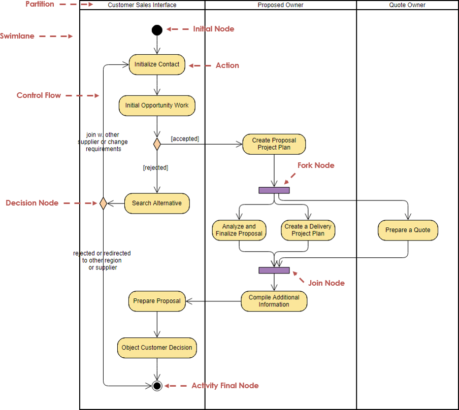
Activity control nodes overview. Activity controls nodes could be used both in as well as in. Initial Node Initial node is a control node at which flow starts when the activity is invoked.
A control token is placed at the initial node when the activity starts, but not in initial nodes in structured nodes contained by the activity. Tokens in an initial node are offered to all outgoing edges. For convenience, initial nodes are an exception to the rule that control nodes cannot hold tokens if they are blocked from moving downstream, for example, by guards. Activities may have more than one initial node.
Object diagram sangat mirip dengan diagram kelas. Perbedaan utama adalah bahwa diagram objek menggambarkan objek dan hubungan mereka. Tujuan utama dari diagram objek adalah untuk memungkinkan analis untuk mengungkap rincian tambahan kelas. Statechart Diagram (State machine Diagram). Setiap node/activity di dalam diagram.

In this case, invoking the activity starts multiple flows, one at each initial node. Note that flows can also start at other nodes, so initial nodes are not required for an activity to start execution. Initial nodes are shown as a small solid circle. Flow final node.
Activity Final Node Activity final node is a control final node that stops all flows in an activity. Activity final was introduced in UML 2.0. An activity may have more than one activity final node. The first one reached stops all flows in the activity.
A token reaching an activity final node terminates the activity. In particular, it stops all executing actions in the activity, and destroys all tokens in object nodes, except in the output activity parameter nodes. Terminating the execution of synchronous invocation actions also terminates whatever behaviors they are waiting on for return. Any behaviors invoked asynchronously by the activity are not affected. If it is not desired to abort all flows in the activity, use flow final instead. Activity final nodes are shown as a solid circle with a hollow circle inside.
It can be thought of as a goal notated as 'bull’s eye,' or target. Activity final node. Decision Node Decision node is a control node that accepts tokens on one or two incoming edges and selects one outgoing edge from one or more outgoing flows.
Decision nodes were introduced in UML to support conditionals in activities. The edges coming into and out of a decision node, other than the decision input flow (if any), must be either all object flows or all control flows.
Each token arriving at a decision node can traverse only one outgoing edge. Tokens are not duplicated. Each token offered by the incoming edge is offered to the outgoing edges. Which of the edges is actually traversed depends on the evaluation of the guards on the outgoing edges. The order in which guards are evaluated is not defined, i.e.
We should not rely on any visual or text description order. The notation for a decision node is a diamond-shaped symbol. Decision node with three outgoing edges and [else] guard. Decision can have decision input behavior specified. Decision input behaviors were introduced in UML to avoid redundant recalculations in guards. In this case each data token is passed to the behavior before guards are evaluated on the outgoing edges.
The behavior is invoked without input for control tokens. The output of the behavior is available to each guard. Because the behavior is used during the process of offering tokens to outgoing edges, it may be run many times on the same token before the token is accepted by those edges. This means the behavior cannot have side effects. Decision input behavior is specified by the keyword «decisionInput» and some decision behavior or condition placed in a note symbol, and attached to the appropriate decision node. Decision node with decision input flow.
If there are both a decision input behavior as well as decision input flow, the token offered on the decision input flow is passed to the behavior (as the only argument if the regular incoming edge is control flow, as the second argument if it is an object flow). Decision nodes with the additional decision input flow offer tokens to outgoing edges only when one token is offered on each incoming edge. Merge Node Merge node is a control node that brings together multiple incoming alternate flows to accept single outgoing flow. There is no joining of tokens. License key spintires mudrunner.
Ban gaye ho tum mere khuda from ranbir kapur song download in mp3 songs. Ke Ban Gaye Ho Tum Mere Khuda. Ke Ban Gaye Ho Tum Mere Khuda. For more lyrics. Tags: Deepika Padukone Download mp3 song Hindi Lyrics Hindi Movie Hindi Song Lyrics Khuda Jaane Lyrics Movie Song mp3 download OTHERS SONG Ranbir Kapoor Song Lyrics. Subscribe to: Post Comments. Bandhe dil ke dhaage tum se Yeh tumhe na jane kya hua Khuda Jaane ke mein fida hun Khuda Jaane mein mit gaya Khuda jaane yeh kyun huwa hai Ke ban gaye ho tum mere khuda (Male) Sajde mein yun hi.
Merge should not be used to synchronize concurrent flows. For example, if a decision is used after a fork, the two flows coming out of the decision need to be merged into one before going to a join; otherwise, the join will wait for both flows, only one of which will arrive. All edges coming into and out of a merge node must be either object flows or control flows.